Solids Flow Stoppages 101
FREE
REGISTERSolids handling problems are common throughout many industries, thanks to a lack of focus around bulk solids training, and common trial-and-error approaches. 70% of all products contain at least some ingredients handled as bulk solids, and studies have shown problems around bulk solids handling has led to higher production costs and lower product quality.
This webinar will provide insights into common flow problems, and offer general steps on how to solve them.

Facts At Your Fingertips: Hopper Outlet Geometry and Arching
When transferring stored bulk-solids materials from hoppers, bins and silos, flow stoppage can occur because of bridging or arching at the vessel outlet. Hopper outlets must be large enough to prevent cohesive arches or stable ratholes from developing. Determining the size and shape of the hopper outlet is critical to ensuring that the bulk material flows. This column provides information on the interplay between bulk material properties and vessel geometry and how those relate to outlet size and shape.
Arch and rathole formation
Bulk solids can experience a range of conditions within a bin, silo or storage hopper. Consolidation pressures range from zero at the surface, to relatively large values at increasing depth within the container. If a solid gains cohesive strength because of the pressures applied to it, an arch or rathole could form. An arch (also called a bridge or dome) is a stable obstruction that forms over the point of narrowest cross-section of the storage vessel (usually the discharge outlet). The arch supports the rest of the bin contents, preventing discharge (Figure 1, left). A rathole is a stable pipe or vertical cavity that empties out over the outlet. Material is left stranded in stagnant zones that usually remain in place until an external force is applied to dislodge them.
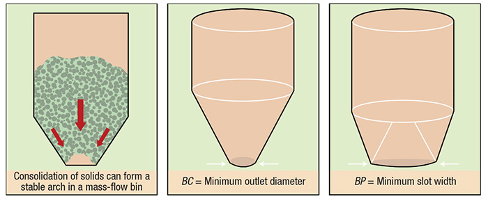
Figure 1. The size of the discharge outlet is a critical element in preventing the formation of an arch in a mass-flow bin
Flow functions
Cohesive strength can be measured as a function of the applied consolidation pressure. By conducting the test over a range of consolidation states, the relationship between consolidation pressure and the cohesive strength of the bulk material can be established, following a procedure established and described by Jenike [1]. In a laboratory, a sample of the material is placed in a direct shear tester and both compressive and shear loads are applied to simulate flow conditions in a container. Once the sample has been consolidated, its strength is measured by shearing it to failure. By repeating this procedure under different conditions, the resulting value of strength versus consolidating pressure (called a flow function) can be developed. The material’s flow function is then used to calculate minimum outlet dimensions.
Once a material’s flow function has been determined, the minimum outlet width or diameter that will prevent cohesive arching can be calculated using the hopper’s flow factor. The flow factor is a function of the powder’s effective angle of internal friction, the hopper angle and the wall friction angle. Typical values of the flow factor range between 1.1 and 1.7. For more on calculating flow functions and flow factors, see Refs. 2 and 3.
Mass- versus funnel-flow bins
Two types of bin flow patterns are possible. A mass-flow bin has a relatively long, tapered discharge section. In mass flow, all of the material is in motion during discharge, so no stagnant regions form. Conversely, a funnel-flow bin has a relatively short converging section. While storage capacity for a given height is greater in a funnel-flow bin, this geometry allows material in the center to move, while material at the walls is stationary. The resultant stagnant regions may interrupt flow.
Compared with a mass-flow bin, there are several potential advantages to using a funnel-flow bin. The relatively shallow hopper requires less headroom for a given storage capacity, and since there is minimal flow along the walls, the likelihood of abrasion and particle attrition is minimized. However, In general, only free-flowing solid materials with large (≥1/4 in.) particle sizes and minimal tendency to degrade (via oxidation, caking and so on) will flow reliably in funnel-flow bins.
Preventing arching
For a mass-flow bin with a circular outlet, the minimum outlet diameter needed to prevent arching is expressed as BC (Figure 1, center). Consider a material whose critical outlet dimension, BC, is 12 in. If this material is placed in a mass-flow bin with an outlet diameter of 6 or 8 in., a stable arch will form. Conversely, if the outlet size is 12 or 14 in., a stable arch cannot form, so the material will flow.
To prevent an arch from forming in a funnel-flow bin, the minimum width of a slotted outlet must be determined. The critical rathole diameter, DF, must also be determined. Ratholing is likely when the diameter of the flow channel (set by the size of the outlet) is smaller than DF.
Planar versus conical flow
The stress needed to deform a given solid also depends on the form of flow channel. In general, a wedge-shaped configuration with an elongated outlet is a more forgiving geometry that can handle a wider range of conditions for a given material without flow stoppages. The minimum outlet width required to prevent an arch from forming in a wedge-shaped, mass-flow hopper is expressed as BP (Figure 1, right). For a given material, this value is usually about half that of BC.
References
1. Jenike, A.W., Storage and flow of solids, University of Utah, Engineering Experiment Station Bulletin, No. 123, November 1964.
2. Carson, J., Pittenger, B. and Marinelli, J., Characterize Bulk Solids to Ensure Smooth Flow, Chem. Eng., April 2016, pp. 50–59.
3. Mehos, G. and Morgan, D., Hopper Design Principles, Chem. Eng., January 2016, pp. 58–63.
Principles of Agglomeration: Pelletizing Processes
Pelletizing, a tumble-growth agglomeration process, offers many potential benefits to processors handling bulk solid materials. This article provides an overview of how agglomerate pelletizing works and the important elements that must be considered
Pelletizing, a form of agglomeration (particle size enlargement) employed to produce a rounded granule, is a valuable operation when working with bulk solids. The technique offers a number of possible improvements to the handling, appearance, application and performance of a wide range of solids materials. The term “pelletizing” is often used interchangeably to refer to various types of agglomeration. This article refers only to pelletizing in terms of tumble-growth agglomeration, which is carried out using a disc pelletizer.
As a form of tumble-growth agglomeration, the pelletizing process is highly customizable and can be used to produce a spherical granular product to exacting specifications.The pelletizing process is most often carried out on a disc pelletizer, typically preceded by a preconditioning step in a pin mixer, and followed by a drying step, with additional process steps possible.
This article looks at the process of agglomerate pelletizing, including the potential benefits that can be realized through pelletizing, how the process works and the key principles behind a successful pelletizing operation.
Processing and material benefits
Pelletizing can be used to impart a number of improvements to both raw materials and end products. While not all products will exhibit all benefits, pelletizing can generally offer the following advantages:
Dust reduction or mitigation. When working with bulk solids in the form of powders or fines, pelletizing significantly reduces, (and in some cases, largely eliminates) dust. Because pelletizing produces a rounded granule, the potential for jagged edges to rub together and break down is decreased. Product integrity is therefore maintained, and material losses are kept to a minimum. Other issues associated with dust, such as health and safety hazards, are also eradicated.
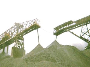
Improved handling and application. Powders and fine materials can present various challenges during handling and application. These include difficulty in transportation, increased product loss, inaccurate and unpredictable application and flowability issues. Pelletized materials flow more readily, promote cleaner handling, and are less likely to become windblown on application (Figure 1). Transportation qualities are also improved, with reduced costs in some cases.
Control of particle properties. Pelletizing is perhaps most widely used as a means of particle engineering, allowing granules to be produced to exacting specifications. Various material characteristics can be fine-tuned to control active-ingredient-release properties or rate of reaction, improve product uniformity, enhance solubility, or even manage packing density and handling characteristics.
When used as an intermediate step within a larger process, pelletizing is also used to control granule properties, such as heat transfer, porosity and density, in order to maximize performance during downstream processing.
Enhanced appearance. Pelletizing is frequently used as a means of improving product appearance. Granules can be produced to be round, smooth and uniform, transforming a regular product into a premium one, with improved flowability, uniformity in size, and less attrition. For this reason, pelletizing is widely used in the fertilizer and soil-amendment industries for high-value products.
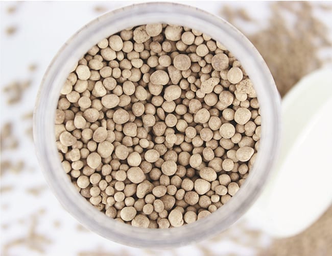
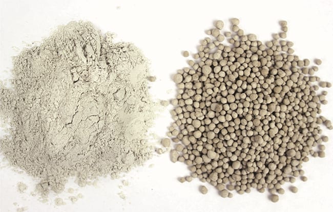
Figure 2. Synthetic gypsum is an example of a commonly pelletized solid material
Commonly pelletized materials. Pelletizing can potentially benefit any bulk solid material that presents handling, application, or performance challenges as a result of its particle characteristics. Solid materials that are frequently pelletized include the following:
- Crushed gypsum (natural or synthetic; Figure 2)
- Crushed limestone
- Nitrogen, phosphorus, potassium (NPK) fertilizers
- Soil amendments
- Flyash
- Iron ore
- Alumina
- Glass
- Silica
- Clays and ceramics
- Electric arc furnace (EAF) dust
- Soda ash
- Carbon black
- Biosolids/manures
- Titanium dioxide (TiO)
- Zinc oxide
PELLETIZING PROCESS
Pelletizing is a non-pressure (also referred to as tumble-growth or agitation) agglomeration technique, meaning that a liquid binder and tumbling action are employed to facilitate the formation of granules. This agglomeration technique differs from pressure-agglomeration methods, which use extreme pressure to cause powder materials to self-adhere into a desired form. Not all solid materials are capable of agglomeration by pressure.
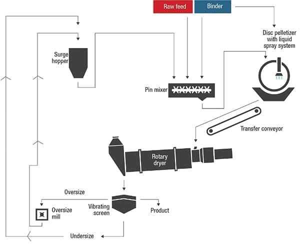
Figure 3. This simplified flow diagram shows a typical disc-pelletizing setup
Primary steps
A typical pelletizing process setup is illustrated in Figure 3. While processes can vary, the most common approach to pelletizing can be broken down into three primary steps: preconditioning, pelletizing and drying.
Preconditioning. A preconditioning step is used to produce a homogeneous mixture of a dry or liquid binder and one or multiple feedstocks. It can also produce “seed pellets,” or nuclei — small agglomerates that serve as the starting particle mass onto which fines will adhere.
Preconditioning is carried out in an industrial continuous mixer, most often a pin mixer — a horizontal, continuous mixer that uses an intense spinning motion to homogeneously pre-mix, densify, and possibly pre-form small agglomerates (Figure 4).
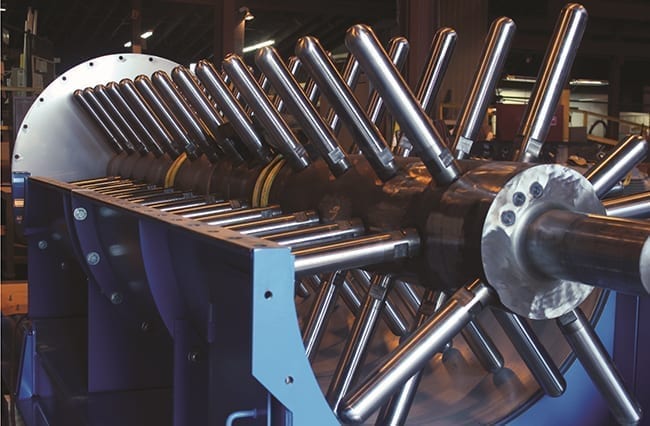
Figure 4. The interior of this pin mixer, including the shaft-in-trough arrangement, can be seen during fabrication
The mixer thoroughly combines the liquid and solid feed components into a homogeneous mixture. As the mixture moves down the length of the mixer, seed pellets begin to form. Upon reaching the predetermined retention time, seed pellets and preconditioned fines are discharged from the mixer and fed to the disc pelletizer.
Pelletizing. The disc pelletizer is a rotating disc mounted onto a stationary base (Figure 5). It is one of the most commonly used types of pelletizing equipment, because it produces a refined granule and offers a highly flexible approach to pelletizing. A number of variables, such as disc angle, speed, feed rate and others, can all be adjusted to control particle size and other characteristics.
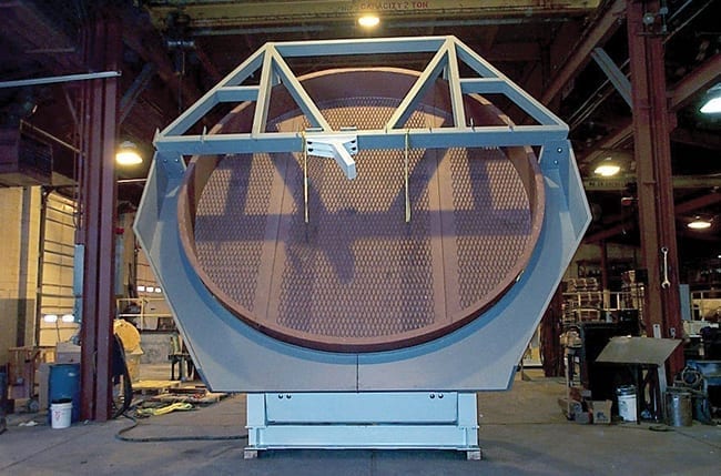
Figure 5. Disc pelletizers, such as the one shown here, have a rotating disc mounted to a stationary base
As the seed pellets are fed onto the rotating disc, the rotation carries pellets partially around the disc and through the feed and spray zones. The binder causes the growing pellets to become tacky, allowing them to pick up more fines as they tumble. This promotes a gradual rolling action that increases granule size by layering (coalescence) — a technique similar to rolling a snowball.
Because of the centrifugal force of the rotating disc, pellets naturally self-classify according to mass and size, with larger and heavier pellets falling sooner as they move closer to the discharge area. Once the pellets have reached the desired size, they are discharged from the disc and fed to a dryer.
Drying. Depending on the process goals and downstream processing, drying may or may not be used in a pelletizing process. The primary objective of drying is to reduce the moisture content of the material and solidify the bond between components. In essence, the drying step “cures” the pellets into their final form. Without sufficient drying, pellets may not hold their shape, could clump together, or may even allow mold or bacterial growth to occur. The drying process also helps the end-product to reach the desired crush strength.
When carried out in a rotary dryer (Figure 6), drying has an added advantage: the rotational tumbling that occurs in the drum may further round and polish pellets.
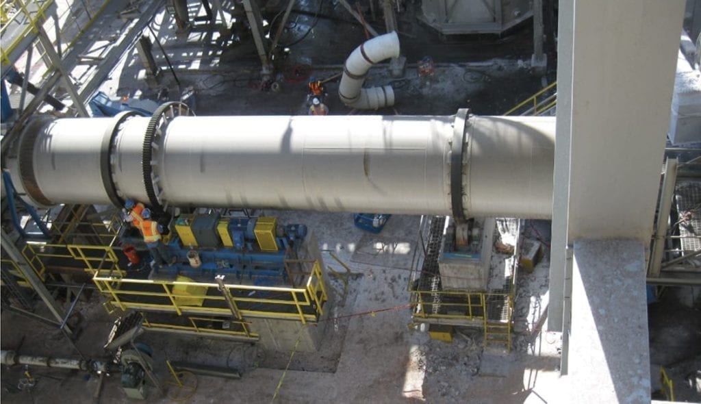
Figure 6. Rotary dryers remove moisture from the agglomerated solids, allowing them to reach the desired crush strength
Controlling particle characteristics. Achieving the desired matrix of end-product characteristics requires a careful balance of process and feedstock parameters. Material and binder feed rates, disc speed and angle, retention time and other variables, are all used to control the properties and overall quality of the end product.
The flexibility of agglomerate pelletizing allows operators to control a wide range of particle characteristics, and to produce an end product that meets a range of specifications for appearance and performance parameters, including the following:
- Green or wet strength
- Dry-pellet crush strength
- Amount of degradation and attrition
- Bulk density
- Solubility
- Flowability
- Particle size distribution (PSD)
- Moisture content
- Surface quality
- Temperature
Pelletizing process add-ons
Various other production elements can be integrated into the pelletizing process to further tailor the process to meet the unique application. Typical integrations are listed below.
Cooling. Depending on the product, a cooling step may be implemented after drying. Cooling helps to prevent product from caking during storage and allows material to be bagged immediately after production.
Coating. Coatings on the agglomerates are sometimes used to further improve granule performance, appearance, or handling characteristics in end products. A number of coating devices are available, with the coating drum being the equipment of choice for superior results.
Recycle. Disc pelletizers generally yield little recycle material, but a recycle circuit can still be beneficial in minimizing off-specification product. A recycle circuit consists of a screening system and mill for reducing oversized granules, as shown in Figure 3. The screen separates oversize and undersize product from on-size product. The oversize product is ground down, typically in a hammer mill, and combined with the undersize material to go back into the process as recycle. Depending on the material, a recycle process may or may not be required to achieve efficient and stable processing. When employed, a recycle circuit can also serve as a buffer in the process, should an upset occur.
PELLETIZING CONSIDERATIONS
There are many aspects to consider in the pelletizing process, but three important considerations stand out as the most influential:
Binder
The binding agent plays a critical role in both the pelletizing process and in the end product quality by influencing pellet formation, green strength and crush strength.
Pellet formation. Binder is used in the pelletizing process to create the tackiness that allows fines to adhere to each other, promoting particle growth. Without this tackiness, pellets and fines would simply tumble with inadequate or non-uniform growth.
Green strength. In addition to aiding in pellet formation, the binder also gives pellets the strength they need to move through the process without breaking down, a property referred to as “green strength” or “wet strength.” Pellets require an adequate green strength to withstand the various drop and transfer points encountered during processing.
Crush strength. The binder also impacts end-product crush strength, solidifying the bond between components upon drying. Some binders may perform well in the pelletizing process, but not produce an adequate crush strength.
The binding agent is a highly customizable part of the process, and often requires testing to determine the best fit. Hundreds of binders are available, and their selection is based on effectiveness, intended product use, cost and availability. The type of binder and the concentration of binder are critical parameters affecting how well the material agglomerates, as well as the amount of dust generated by the pellets upon drying.
Moisture
Controlling the moisture content of the material throughout processing is the foundation of achieving desired product characteristics and ensuring that the process operates smoothly.
All materials have a unique range of moisture within which they will successfully agglomerate (assuming they will agglomerate) via tumble-growth techniques. Some organic materials, like compost, animal feeds and sawdust, have a wide range of acceptable moisture content in which they will agglomerate, while others, like iron oxide, silica dust, many clays and fertilizers, require a very narrow window of moisture content. A delicate balance must be achieved: too much moisture and the material may form clumps or become a slurry; too little moisture and agglomerates will not form properly, or may not form at all.
Since moisture will be added in the form of a liquid binder, the starting material feedstock must fall below the identified range of moisture at which the material will agglomerate. The addition of binder will then bring the material into the ideal moisture range for agglomeration to occur. Consequently, materials containing a moisture content higher than what has been identified as acceptable will require some form of moisture reduction prior to pelletizing.
Preconditioning
Preconditioning is not a requirement in all pelletizing production lines. Some operations simply feed raw feedstock onto the disc pelletizer, omitting the preconditioning step in the pin mixer. However, preconditioning does offer significant value, and may be required depending on the desired end-product characteristics.
The inclusion of a preconditioning step provides several key benefits to the pelletizing process:
Improved product uniformity. While disc pelletizers do promote blending of fines and binder, they are not intended to thoroughly mix the different feed materials. As a result, pelletizing operations not utilizing a preconditioning step may experience an uneven distribution of binder in pellets, resulting in non-uniform product formulation and variable crush strength.
The addition of a preconditioning step ensures that the binder and fines are thoroughly combined into a homogeneous mixture before processing on the disc pelletizer, promoting a highly uniform product.
Increased production. The addition of a preconditioning step also increases production compared to the use of a pelletizer alone. When using a pelletizer alone, binder and fines are added at a continuous, predetermined rate. Because the addition of binder must be gradual, so as to avoid adding excess moisture to the disc, growing material from fines to the desired-size pellet can take a considerable amount of time. With a preconditioning step, seed pellet formation happens much more quickly, leaving the disc pelletizer with the sole job of increasing pellet size, enabling production rates to increase.
Reduced binder. Part of the intent in pelletizing is to increase product density. When utilizing a pelletizer alone, density is created through the addition of the liquid binder.
Conversely, when a preconditioning step is implemented, density is created not only with the binder, but through the action of the mixer, ultimately reducing the amount of binder required to reach the desired density.
Material influence. Every solid material presents unique challenges when it comes to pelletizing agglomeration. The feed makeup, consistency, moisture content, particle size distribution, and many other factors, will all influence how a material responds to the pelletizing process.
Some solid materials will readily agglomerate, while others simply may not. Some materials will undergo a reaction between constituents that causes pellets to exhibit a higher-than-desired crush strength or other unpredictable attribute. Still others may only agglomerate with significant modifications to the formulation to the product makeup.
Additionally, some materials may require special modifications to the equipment. This is often the case with abrasive materials that could cause excessive wear if not factored into the design process.
For these reasons, testing at batch and continuous scale is often a necessary part of process development for pelletizing lines.
Edited by Scott Jenkins
Authors
 Chris Kozicki is a process sales engineer with FEECO International (3913 Algoma Rd., Green Bay, WI 54311; Email: [email protected]; Phone: 1-800-373-9347), specializing in tumble-growth agglomeration. He has been with FEECO for over 30 years. Kozicki is an active member of the agglomeration community and former president of the Institute for Briquetting and Agglomeration (IBA).
 Ron Eichhorn supervises the FEECO Innovation Center (same address as above), where he oversees agglomerate testing for hundreds of materials. Having been with the company for nearly 40 years, Eichhorn has become a global expert in pelletizing and travels the world conducting training on the topic.
 Carrie Carlson is a technical writer who has been with FEECO (same address as above) for nearly a decade. She works closely with engineers and process experts to turn complex ideas into easy-to-understand literature.

Air Movers for Dilute-Phase Pneumatic Conveying
Selecting the best air mover for a bulk-solids pneumatic-conveying application is a critical design decision. Provided here is information on three classes of air movers when dilute-phase pneumatic conveying is required
In a typical bulk-solids pneumatic-conveying system, an air mover is used to generate the necessary air flowrate and pressure required to transport a solid material through a specific pipeline distance at a given rate. Designing a successful pneumatic conveying system depends on specifying the correct air mover, in terms of volumetric flowrate, pressure and motor size. A wide range of machines is potentially capable of meeting the requirements of the duty. However, not all air movers are suited to pneumatic conveying applications. Therefore, understanding the design and operating characteristics of various air movers is the key to successfully selecting the right machine.
This article discusses the operating mechanisms and characteristics of three different types of air movers for dilute-phase pneumatic conveying: centrifugal fans and blowers; regenerative blowers; and positive-displacement (PD) blowers. Numerous air movers are available on the market for dilute-phase conveying applications. In many cases, two or even three types of air movers can perform the same job, delivering the accurate amount of air flow at the correct pressure. However, their capital investment and operation costs, as well as machine efficiency and reliability, will certainly be different. Understanding their mechanisms of operation can assist in choosing an effective air mover for the successful design and operation of any pneumatic conveying system.
Air mover types and uses
A European Union study has shown that 15% of the world-wide energy consumption is used to produce compressed air. The typical air movers — fans, blowers, and compressors — are widely used in various industries, such as agriculture, energy, mining, chemical production and others. Air movers typically used for pneumatic conveying applications include centrifugal fans and blowers, regenerative blowers, PD blowers and PD compressors. The air mover is often the largest single item of capital expenditure in a pneumatic conveying system, and the potential conveying capacity of the system is mainly dependent upon the air mover selected.
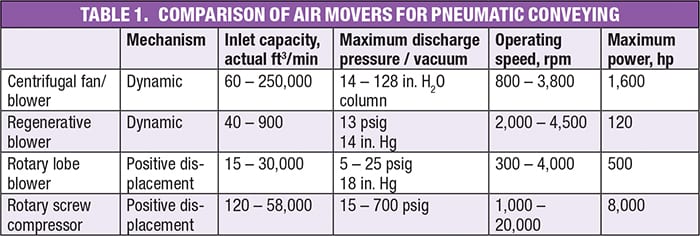
Centrifugal fans and blowers produce high volumetric flowrates at low pressures, usually for conveying systems with very low solids-to-air ratios, such as dedusting and milling. PD blowers produce medium volumetric flow rate at medium pressure, accounting for over 80% of pneumatic conveying installations, typically for dilute-phase systems. PD compressors, usually reciprocating or rotary-screw machines, can produce the highest pressures required for long distance or dense-phase conveying systems. Regenerative blowers are a niche air mover, which can provide small flowrates at low to medium pressure in a very cost-effective way.
Table 1 lists the types of air movers that are used for pneumatic conveying applications and their characteristics, such as compression mechanism, air flow and pressure ranges.
All air movers are similar in that they are moving and compressing air through internal chambers (a PD blower is different, because its air is compressed at the discharge port, not in the internal chamber). For the purposes of specifying an air mover for pneumatic conveying, air can be treated as an ideal gas, which obeys the equation of state:
ρ = P /R T (1)
where P is pressure; ρ is density; R is the gas constant per unit mass; and T is temperature.
Centrifugal blowers and fans
Centrifugal blowers and fans are aerodynamic-type air movers and are widely used on short-distance, very dilute-phase systems. The solids-to-air ratio for a fan conveying system is typically less than 1.2 to 1. If its feedrate is steady and smooth, the solids-to-air ratio can be up to 2 to 1. Fans may be used for both positive-pressure and negative-pressure conveying systems. The centrifugal fan/blower used in pneumatic conveying applications, are normally of the radial, flat-bladed type, similar to the one shown in Figure 1. At a given speed, these centrifugal fans or blowers will draw the same volume of air at a given pressure.
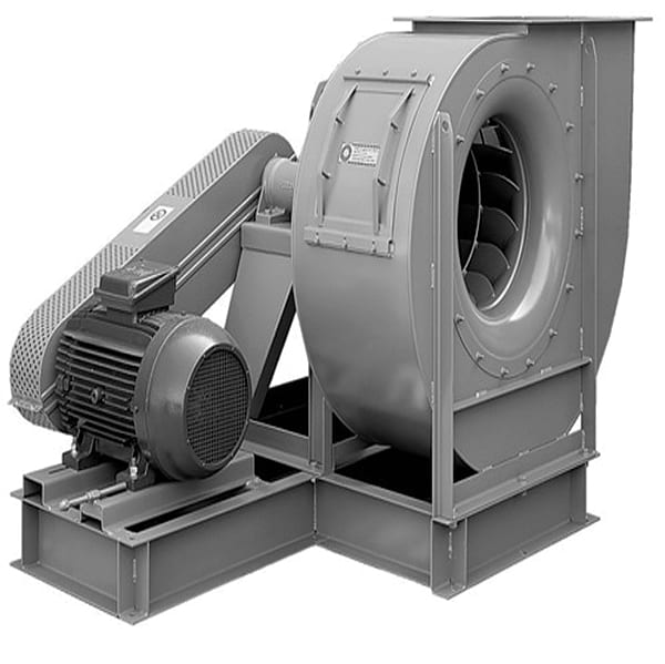
Figure 1. Centrifugal fans, such as the one shown here, are one possible option for use in a pneumatic conveying application
The basic function of a centrifugal fan/blower is to produce kinetic energy by the action of centrifugal force. Its impeller and channels convert this kinetic energy of the air into potential energy (in the form of pressure) by efficiently reducing the velocity of the flowing air. For example, a fan with a wheel diameter of 30 in., running at 3,000 revolutions per minute (rpm), has an impeller tip speed as high as 23,562 ft/min, which leads to a velocity pressure of 34.62 in. H2O (inches of water column). If the ultimate fan air-outlet velocity is 4,000 ft/min, the total kinetic energy converted to potential energy is 33.62 in. H2O.
Figure 2 shows the operating characteristics of centrifugal fans and blowers. The air flowrate is highly dependent upon the conveying-line pressure drop. If the solids feedrate to the system should become excessive for any reason, causing the system pressure drop to increase significantly, the air flowrate becomes so low that the material falls out of suspension. This increases the risk of blocking the pipeline. Because the residence time of the material in the conveying pipeline is very short, a sudden surge in feedrate can quickly have a significant effect on the pressure required. Therefore, centrifugal fans and blowers can only be used for applications with low pressures and low solids loading, and cannot be used reliably for heavy-duty conveying. Steady and controlled material feed can minimize feed surge and ensure a reliable centrifugal fan/blower operation. Due to this airflow-pressure relationship, centrifugal fans/blowers may not recover from emergency shutdown when conveying solids.
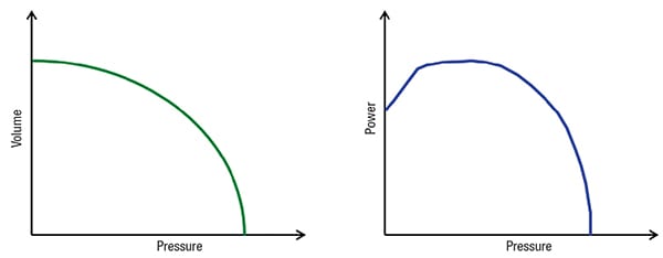
Figure 2. The plots show the operating characteristics of fans (left) and blowers (right). Air flowrate is highly dependent upon conveying line pressure drop
The relationship between fan power and system pressure drop is also shown in Figure 2. As pressure decreases, the power increases. This is because at low pressure, the fan has to move a large amount of air, which consumes a lot of power. This is also why sometimes operators must choke-start a fan to minimize the power drawn when a small motor is installed. The lowest power drawn happens when the system pressure is the highest. Therefore, centrifugal fans and blowers are unloaded by closing either the inlet or the outlet.
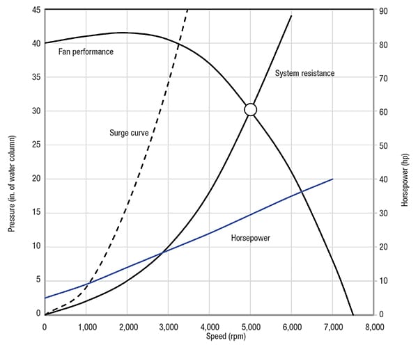
Figure 3. Fan performance curves, such as the one here, shows the relationship between the air volume that a fan will deliver, and the pressure generated at various air volumes
Fan performance curve
The fan performance curve (Figure 3), is the most valuable information supplied by fan manufacturers. These curves show the relationship between the air volume that a fan will deliver, and the pressure generated at various air volumes. The curves also show power for a given air volume. A system resistance curve is always included, and this usually is associated with a specific fan application. The system resistance is the sum of all pressure losses through the pipeline, including all pipeline elbows, filters, dampers and any other element that resists flow. The fan will operate at the point where the system resistance curve intersects the fan curve.
For some fan curves provided by fan manufacturers, there is a fan surge curve (the circle in Figure 3). Selecting fans such that they operate close to, or to the left of, the surge curve, is not recommended. Referring to this surge curve helps the designer to ensure selecting fans that are stable and will not go into surge with a minor change to the system.
The fan brake horsepower can be found from the power curve in the fan performance diagram. By using the calculated system pressure drop and required air flowrate, you can also estimate it according to the following equation:
BHP = P × Q / 5,085 (2)
where BHP is the fan brake horsepower (hp); Q is the fan flowrate (ft3/min), and P is the fan operating pressure, (inches of water column). Equation (2) gives an approximate value of the fan motor power required. For example, in the previous case, if air flowrate is 11,000 ft3/min, the BHP for the fan is about 43.26 hp.
Fan laws
There are two reasons why a fan’s performance may need to be changed:
- The system requires additional airflow
- The actual system resistance pressure is different from the design value
When these situations occur, it is important to understand how they can affect the fan’s performance. The effect can be shown by using the Fan Laws, shown by Equations (3a), (3b) and (3c).
Q2 = Q1 × (N2 /N1) (3a)
P2 = P1 × (N2/N1)2 (3b)
BHP2 = BHP1 (N2/N1)3 (3c)
where Q1 and Q2 are the fan volume, ft3/min; P1, P2 are the fan operating pressure, inches water column; and BHP1 and BHP2 are the fan brake power, hp.
For example, a fan installed in a conveying system running at 1,500 rpm is to handle 15,000 ft3/min at 16 in. water column and 45 BHP. What fan speed is required to move 20% more air, or 18,000 ft3/min, through this system? What is the new fan operating pressure and fan BHP? Using the fan law equations above, we obtain the following:
• N2 = 1,800 rpm
• P2 = 23.04 in. water column
• BHP2 = 77.76 hp
Therefore, according to the fan laws, in order to use the original fan, its speed must be increased from 1,500 rpm to 1,800 rpm, and the BHP increases 72.8%, from 45 hp to 77.76 hp. Thus, with a 20% air flowrate increase, the motor must be upgraded from 50 to 100 hp. Of course, make sure the new speed value is less than the maximum allowable speed for the existing fan.
Temperature and altitude effects
In each fan catalog, the performances tables are based on standard air density, which is defined as dry air at 70˚F at sea level (29.92 in. Hg barometric pressure). This is equal to 0.075 lb/ft3 density. The fan performance tables provide the fan speed and brake power requirements for the given volumetric flowrate value and static pressure, at standard air density.
When the fan performance is not at standard conditions, the performance must be converted to standard conditions before using the fan performance tables. The fan must be selected for the given rate of flow, but for an equivalent static pressure. The equivalent static pressure is the working static pressure corrected for temperature and altitude. The fan performance is converted to standard conditions by either using the correction factors in the temperature and altitude correction chart, which are usually included in fan catalogs, or by dividing by the calculated correction factors: temperature factor = the ratio of standard absolute temperature (°R) to working absolute temperature (°R); altitude factor = the ratio of barometric pressure at the given elevation to that at sea level (29.92 in. Hg), or the ratio of the density reduction factor shown in some tables.
To illustrate, we can use the same example as mentioned previously, but now assume that the fan is operating at 300°F and 4,000 ft elevation above sea level. In this case, what are the fan speed and the motor size? Since this fan is not operating at standard conditions, we cannot use the fan performance table directly. The 16 in. static pressure has to be corrected by both the temperature and altitude factors. The temperature factor is 0.697 (= 530°R/760°R) and the altitude factor is 0.864 (= 25.84 in. Hg/29.92 in. Hg).
The equivalent static pressure, therefore, becomes the following:
Pequivalent = 16/(0.697×0.864) = 26.566 in. H2O (4)
Now we can use the fan performance in Table 2 to interpolate the fan speed at 1,845.698 rpm and the brake horsepower at 76.934 hp. The brake horsepower at the working static pressure would be corrected as follows:
BHP real = 76.934 × 0.697 × 0.864 = 46.355 hp (5)
A 50-hp size motor would be enough for this job. However, if the fan were operated with cold air, the horsepower drawn, 66.443 hp (= 76.934 × 0.864), would exceed the capacity of the motor and the airflow to the fan would have to be throttled until the equipment warms up to the correct temperature.
If a centrifugal fan/blower is used for vacuum-conveying, negative static pressure exists on the inlet side of a fan, and an additional correction for a lower density should be made. When negative pressure is less than 20 in. water column, this factor (called rarefication factor) is usually considered negligible, unless the system designer is calculating to extremely close tolerances. The factors apply to static pressure and brake power in the same manner as temperature and altitude corrections. You can find the rarefication factor either in fan catalogs or by using the following formula: rarefication factor = the ratio of working absolute pressure to standard absolute pressure.
Actually, all of the corrections are based on the inlet density changes due to various temperatures and pressures (altitude, inlet vacuum). The changes are reflected from the assumed ideal gas in Equation (1).
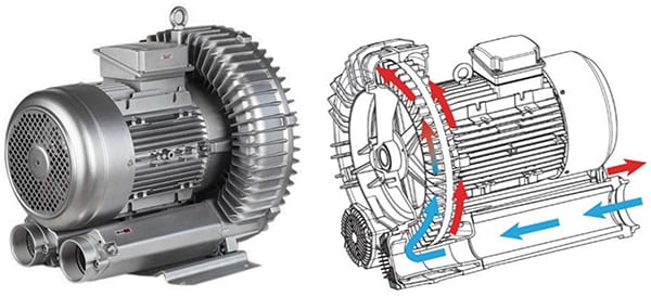
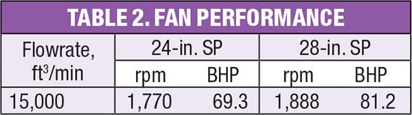
Figure 4. Regenerative blowers are used with low airflow and medium pressure
Regenerative blowers
The regenerative blower is also an aerodynamic-type air mover, and is mainly used on short to medium distance, dilute-phase systems, such as drum/bag dump stations and solids conveying eductors (Figure 4). The solids-to-air ratio for a regenerative blower conveying system is typically less than 4 to 1, and its maximum air flowrate is about 900 ft3/min. Regenerative blowers have parallel inlets and outlets that are positioned perpendicularly to the rotation of the impeller. Regenerative blower installations are typically in a direct-drive design, as shown in Figure 5. However, it can also be a belt-drive design. The impeller in the direct drive construction is mounted directly on the electric motor.
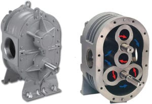
Figure 5. The exterior (left) and interior (right) of the twin-lobe Roots blower are shown here
Regenerative blowers have a slightly different mechanism than centrifugal fans/blowers for compressing air. The impeller consists of numerous radial blades along the circumference of the impeller. The impeller spins within a housing that consists of an inboard and outboard “channel.” As the impeller passes the inlet port, air is drawn in. As the impeller rotates, air is captured between each blade on the impeller and is pushed both outward and forward into the channels. The air then returns to the base of the blade. During this process, a portion of the kinetic energy (air velocity) is converted to potential energy (air pressure). This process is repeated over and over as the impeller spins. While each blade-to-blade regeneration “stage” results in only slight pressure increases, the sum total, from air entry to outlet can yield continuous operating pressures of up to 13 psig or vacuum to 14 in. Hg.
Performance curves for regenerative blowers are generally better than those shown for the centrifugal fans and blowers shown in Figure 3, but are not as good as those for positive-displacement machines. In other words, its air flowrate is less dependent upon the conveying-line pressure resistance. Therefore, it can be used for higher-solids-loading applications than a centrifugal fan/blower.
Among the most significant benefits of a regenerative blower is that it is virtually maintenance-free. There is only one moving part (the impeller), which does not come in contact with the housing channel and is essentially wear-free. Regenerative blowers can operate for up to 40,000 hours without requiring service — a properly installed regenerative blowers is capable of providing years of service-free operation.
Regenerative blowers are oil-free and have no complicated intake/exhaust valve. They can be mounted in any plane and, with dynamically balanced impellers, generate little vibration. As a non-positive displacement compressor, the discharged air, like centrifugal blowers, is pulsation-free, and therefore, generates extremely low noise. Even without an acoustical cover, the typical free field noise level is only 82 dBA at 3 ft distance.
Due to the tight internal tolerances between the impeller and housing, it is important that foreign material not be allowed to enter the blower. A filter, such as a 10-µm filter, should always be installed before the inlet of a regenerative blower.
Overpressurization can also cause a catastrophic failure. Most blowers must have air passing through to cool it. Without it, heat will build up, causing the impeller to expand at a faster rate than the blower housing. If this continues, the impeller will eventually lock up with the housing and cause the blower to fail. A relief valve (either vacuum or pressure) will prevent overpressurization and will allow air to pass through the blower.
Positive-displacement blowers
Positive-displacement (PD) blowers, like its name implies, are positive-displacement-type air movers, and are probably the most commonly used type of compressor for dilute-phase pneumatic conveying systems, where the operating pressure typically does not exceed about 18 psig. That pressure is an ideal match with the pressure capability of conventional rotary valves. The PD blower is essentially a constant-speed machine that delivers a relatively constant volume of air over a range of discharge pressures (Figure 6). The solids-to-air ratio for a PD blower dilute phase conveying system is typically from 2:1 to 6:1, up to 10:1 in some cases. PD blowers have also been used for short-distance, dense-phase pneumatic-conveying applications, such as hopper truck unloading. The resistance of the system to which the blower is applied determines the operating pressure.
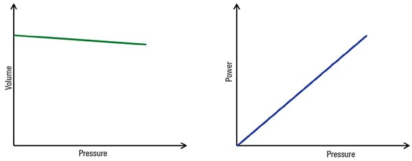
Figure 6. The graphs show operating characteristics of PD blowers, which deliver a practically constant flowrate, independent of disharge pressure conditions
The twin-lobe Roots-type blower is the oldest and most widely used PD blower. This type consists of a pair of involute profiled (shape of 8) lobes/rotors that rotate inside an oval-shaped casing. One lobe is the driving lobe, which is powered by the external power source, while the driven lobe is driven by a pair of equal-ratio gears. Both the lobes rotate at the same speed, but in opposite directions.
PD blowers have a totally different mechanism than centrifugal fans/blowers and regenerative blowers for compressing air. As the rotors rotate, air is drawn into the inlet side of the cylinder and forced out the outlet side against the system pressure. With each revolution, four such volumes are displaced. The air, which is forced out, is not allowed to come back due to the small internal clearance within the internals of the machine (except for a very small amount called “slip”). There is no change in the volume of the air within the machine, but it merely displaces the air from the suction end to the discharge end, against the discharge-system resistance. In other words, no compression takes place in the machine. However, as the discharge end is reached, compression occurs when the high pressure air in the outlet pipe flows back and meets the trapped air. Due to this shock compression, the thermodynamic efficiency of the machine is relatively low, and it generates relatively high pulsation and high noise. In order to reduce the pulsation level and noise, three-lobe and four-lobe rotors have been introduced. This allows the lobes to have a slight twist along the rotor axes, which reduces pulsing in the input and output. Since the lobes run within the casing with finite clearances, which are controlled by the gears, no internal lubrication is required. The air is thus delivered free of oil.
Unlike centrifugal fans/blowers, PD blowers deliver, practically, a constant flowrate independent of the discharge pressure conditions. There is a slight flowrate reduction with the increase of system pressure. This is because a very small amount of air “slip” back through the clearance at high discharge pressure. Therefore, in PD blowers, the flowrate is dependent mainly on its operating speed.
The relationship between PD blower power consumption and system pressure drop is shown in Figure 6. Power consumption in PD blowers is proportional to system pressure drop. The lowest power drawn happens when the system pressure is the lowest (in other words, when there is no solids loading in a pneumatic conveying system). Therefore, PD blowers are generally selected for the maximum system pressure, which they may encounter during operation. When in operation, the blower offers considerable power savings, since the power consumed by it depends upon the actual working pressure under which it operates, and not the rated pressure. This is totally different compared to other air movers, such as reciprocating compressors, sliding-vane and screw-type compressors, in which the compression ratio is fixed and the suction air is compressed, according to the compression ratio, regardless of the load conditions. A fixed power is thus consumed by these types of compressors.
PD blower performance curve
The PD blower curve supplied by blower manufacturers typically contains all the information you need to choose the right blower, motor and cooler, if necessary. In a dilute-phase conveying application, after the desired air flowrate and system pressure are determined, it is time to select the PD blower to move bulk solids to the destination reliably. First, find a PD blower that has the right range of air flowrate and pressure from manufacturer catalogs. Then use its blower performance curve to select the right blower speed and associated motor size.
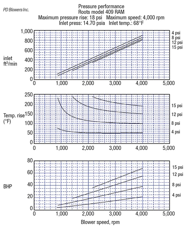
Figure 7. The graph shows a blower performance curve for a PD blower
Figure 7 shows the pressure performance curve for the Roots Model 409 RAM blower. For instance, if the required air flow is 600 inlet ft 3 /min and system pressure is 8 psi, what are the blower speed and motor size? Start on the upper chart in Figure 7 from the left vertical coordinate and find 600 inlet ft3/min, move horizontally to the right and find the intersection with the 8-psi pressure curve. Then move straight down to find the right blower speed (rpm) at the horizontal coordinate, 3,000 rpm. This is the speed the blower has to run in order to deliver 600 inlet ft 3 /min air flow at 8-psi system pressure resistance.
The input power for a PD blower is largely dependent on the total pressure across the machine. To find the blower power consumption for the blower performance curve, use the lower graph in Figure 7 and move up from 3,000 rpm point. When it intersects the 8-psi curve, move left to find the blower BHP from the left vertical coordinate (28 BHP from Figure 7). To have a decent safety margin and also for possible future capacity release, a 40-hp motor is recommended.
The brake horsepower required to drive the blower can also be estimated quickly by Equation (6):
BHP = ( P× Q) / 229 × eff.% (6)
where P is the system pressure drop, psi and Q is the blower inlet-air flowrate, ft3/min and eff% is the blower efficiency (65–80%). If we use 75% as the blower efficiency here, the calculated BHP is 27.95 hp.
When air is being compressed, a large portion of the energy of compression is dissipated in the form of heat to the gas. The temperature rise of the discharge air in a PD blower is largely dependent on the differential pressure across it. Knowing the value of the temperature rise is critical, since the blower has limits on thermal growth. At high temperature, the lobes can expand into the headplates, causing the unit to seize and possibly causing extensive damage to the unit. In general, the blower average temperature, (Tinlet + Tout)/2) should not exceed 250°F. At temperatures higher than that, a larger blower should be used, or the inlet gas should be cooled.
The temperature rise can be found from the blower curve. Move up from its speed-rpm point, until it reaches the second system-pressure value, then move right to find the temperature rise from the right vertical coordinate, as shown in Figure 8.
Temperature rise (∆ T, in°F), at operating conditions can also be approximated by the following equation:
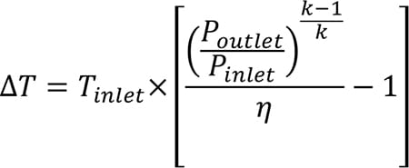 (7)
(7)
where η is the entropy efficiency for PD blower, (70~90%); Pinlet is the actual absolute inlet pressure in psia, and Poutlet is the actual absolute outlet pressure in psia, k is the ratio of the specific heats (for air, 1.4).
The blower performance curves are also based on standard conditions. When the blower operates at non-standard conditions, such as high or low temperature and high altitude, the calculated blower air flow is the actual cubic feet per minute (ACFM), which need to be converted to the blower inlet air flow (ICFM) at standard conditions. Unlike the correction for centrifugal fan to change the pressure, here we keep the pressure unchanged and correct the air flowrate directly. Then, we can specify the correct blower model using the typically increased air flowrate, as well as its speed and motor.
Blower protection
Several ancillary devices are required to protect a PD blower:
Inlet filters. Inlet filters and a filter pressure gage are critical elements in the proper operation of a PD blower. Inlet filters clean the incoming air or gas to minimize the entrance of larger particles into the blower. This filtration is critical to prevent large objects or particles from entering the gas chamber and causing material buildup on the impellers. If the particles are too large, they can cause the unit to seize, which could result in a costly repair. Dirty filters will increase your power consumption and can cause excessive temperature rise on your PD blower. Filters should be cleaned or changed once the pressure drop exceeds 15 in. water column. A filter pressure gage will visually indicate when the filter needs to be changed or cleaned.
Check valves. Check valves are necessary to prevent bulk solids from entering the blower. Make sure to install the valve in the correct direction. A check valve will add about 1 in. water of pressure drop into the system.
Relief valves. Relief valves, either pressure or vacuum, are very important to prevent the damage of the blower unit. Relief valves are available in two types: spring or weighted type. Spring-type valves are typically the most popular and least expensive for a given flow and pressure. Weighted relief valves are available for pressure systems only. They must be mounted in a vertical upright orientation to function properly.
Connectors. Flexible connectors are used to isolate the blower from other system components. This isolation allows for thermal expansion and misalignment of the piping. The two most commonly used connectors are a flexible hose and a single arch-type expansion joint. Flexible hose is typically used for pipe sizes up to 5-in. Schedule-40 pipe. A single arch-type expansion joint is typically used on a flanged connection. Compression-type couplings are also used. These can provide mechanical support, but also allows for thermal expansion.
Noise reduction
PD blowers have two rotors that trap a “pocket” of air each time they sweep by the inlet and discharge connection. A pressure pulse is created each time this occurs. This pressure pulse creates noise and vibration. Blower silencers can be used to reduce this noise and vibration. A silencer will add about 5 in. of water of pressure drop into the system. Sometimes a sound enclosure, which can achieve 25–30 dBA sound reduction, is necessary to provide a low-noise working area near the blower.
Edited by Scott Jenkins
Author

Gary Liu is principal consultant for solids processing and handling at DuPont (1007 Market Street, Wilmington, DE 19898; Phone: 302-695-7627; Email: [email protected]). He has more than 19 years of experience in solids handling and processing, both in research and development and commercial manufacturing. Liu is a registered professional engineer in the state of Delaware and holds a Ph.D. in mechanical engineering from the New Jersey Institute of Technology in Newark, N.J.
Preventing Flow Stoppages in Powder Handling Processes
Predicting powder flow behavior is important to successful solids-handling processes. Provided here is a review of shear-cell testing and how the technique can be used to predict arching, ratholing and other behaviors
The phrases “failure to discharge” and “erratic flow in the hopper” are sometimes heard from frustrated production-floor workers when powder processes start to misbehave. Taking corrective action for these types of problems may involve shutting down the process to investigate the root cause. Ideally, processors would identify suspect powders prior to processing, thereby avoiding costly downtime. Traditional methods for predicting flow behavior — flow cup, angle of repose and tap tests — are giving way to shear-cell testing, which measures inter-particle sliding friction, as well as powder-to-hopper wall interfacial friction. This article explains the science behind shear-cell measurements. Predictions for density-compaction ratio, potential arching dimension or rathole diameter, and design requirements for hopper half angle to achieve mass flow are reviewed.
Types of powder flow behavior
Figure 1 illustrates two common flow types. “Core flow” is the default discharge pattern experienced on the production floor. When the feed bin is filled with powder, the material’s behavior can be characterized as “last-in, first-out.” Powder flows from the top of the vessel downward through a vertical channel above the outlet. Material around the walls remains static until the fill level reduces to expose stationary particles, which now become the top free surface. If powder is refilled into the hopper regularly, material near the bottom of the vessel may remain in place for long periods of time until the vessel drains to empty. Potential dangers include compaction of the stationary powder and potential caking or bridging in the hopper outlet. Powder that remains stationary for too long a time risks spoilage or other problems related to aging material.
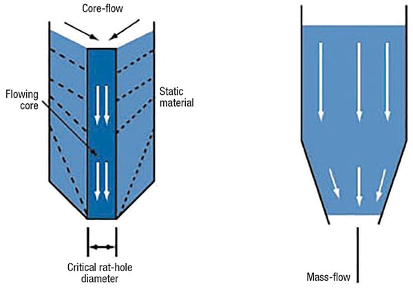
Figure 1. The diagram shows core flow (left) and mass flow (right) patterns
Many companies in the chemical process industries (CPI) experience flow problems and core flow behavior due to the cohesive nature of powders, such as carbon black and calcium carbonate.
Mass flow is the preferred discharge pattern. The flow behavior in this case can be characterized as “first-in, first-out.” In mass flow mode, powder throughout the bin is in motion simultaneously, including particles in close proximity to the wall. One important advantage of mass flow is that blended powders undergoing mass flow in a hopper generally maintain their compositions, whereas blended powders tend to segregate with core flow.
Time consolidation
Consolidation of powders can occur when powders fill and occupy a vessel. Powders may increase their internal strength (also known as “failure strength”) from the initial moment they fill the bin. The weight of powder pushes down on particles below due to gravity, so powder at the bottom of the vessel experiences the highest compaction stress. Air gradually squeezes out from empty spaces between particles. Consolidation takes place as particles move closer together. Increases in powder strength depend on the amount of time the powder remains stationary and undisturbed. Like a packed snowball, the powder can reach a state where it cakes and resists movement when discharge out the hopper finally commences.
Powder density
Measuring the compressibility of a powder is one experimental way to predict flow behavior. The greater the extent that a powder compresses together, the greater its powder strength. One possible consequence of this higher powder strength is that powder flow becomes increasingly difficult.
The tap test is an established method for measuring compressibility of powders. In a tap test, an empty cylinder of fixed volume is filled to the brim with the powder. The cylinder is tapped up and down a defined number of times (perhaps 100 or 150 repetitions). After the tapping, the reduced fill level of the powder is measured, then divided by the initial fill level to calculate the compressibility ratio. Tap tests can be accomplished relatively quickly, but they provide only two data points on a curve — namely the loose fill density and the compacted density after a defined number of taps. The tap test may be run several times to determine the steady state for maximum compaction after the defined number of taps.
A rule of thumb is that powders that compress more than 35% from the loose-fill condition in the tap test may exhibit flow behavior problems in powder handling operations. An observation of 50% compressibility is a sure indication that processing will have challenges related to powder flow, especially if there is any downtime after the powder is placed in the bin or hopper.
Powder mechanics and obstructions
Fundamental to predicting powder flow is analyzing inter-particle friction. Resistance to movement in powder processing is due to sliding friction between particles, as well as interfacial friction between the powder and the hopper surface.
Three types of obstructions may occur to prevent discharge from a bin. The “mechanical arch” involves large particles interlocking with each other and blocking the outlet. A “cohesive arch” occurs when powder at the bottom gains sufficient strength due to consolidating stresses that it solidifies and bridges the outlet. “Rathole” formation takes place when the powder in a vertical core above the outlet discharges and powder throughout the rest of the vessel remains static.
Segregation is a problem that may result during blockages. Particles of differing shapes and sizes separate across the cross-section of a vessel or hopper. One typical pattern of segregation is an increase in fine (smaller) particles near the central axis of the vessel and a greater concentration of coarse (larger) particles near the outer walls.
Annular shear cell
Over 50 years ago, the minerals industry devised a technique to quantify sliding friction behavior during powder discharge from a bin by measuring aggregate shear forces between particles in a controlled sample. This initial experimental work led to the development of the “annular shear cell,” a chamber that holds the powder sample, allows it to be consolidated, and then exposes it to uniform shearing forces in order to measure the yield stress necessary for relative movement. Figure 2 shows typical shear-cell components.
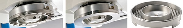
Figure 2. The components of a shear cell tester include the vane lid (left), wall friction lid (middle) and the trough (right)
The annular cell in which the powder is placed has a well-defined volume. Various chamber sizes are available to accommodate whatever amount of powder is available for testing. The shear cell is then placed onto the “powder flow tester” instrument. A lid affixed to the compression plate on the instrument descends onto the sample and consolidates the powder to a defined stress value. Reduction in the sample volume as powder particles push together is automatically measured by the instrument. This procedure for consolidating the powder using a defined stress is repeated multiple times to verify that the powder has achieved “critical consolidation,” meaning that particles have reached an equilibrium condition with relative spacing.
There are two types of lids used on the instrument, one to measure interparticle friction (vane lid), the other to measure wall friction, which simulates powder sliding against the hopper wall prior to discharge (wall friction lid). The test procedure, regardless of lid type, involves compressing the powder at increasingly higher stress levels to evaluate change in powder strength. At each consolidating stress level, the trough rotates slightly on the instrument turntable and powder friction is measured.
Density measurement
As the annular shear-cell test progresses, the reduction in sample volume is measured and the powder bulk density is calculated. Figure 3 shows graphical data for different powders from the density test. The x-axis is the consolidating stress, in units of kiloPascals (kPa) and the y-axis is the bulk density in kilograms per cubic meter. Software used with powder flow instruments typically has flexibility with regard to the choice of scientific units when reporting data. The loose-fill density at the beginning of the test is shown by the left-most point on the graph, representing the powder condition when it is first poured into the bin. Bulk density values increase as the test progresses and normally approach an asymptotic value as consolidation of the powder reaches a maximum. The amount of consolidation between the loose-fill condition and the maximum density is expressed as a compressibility ratio. This numerical value is comparable to industry standard calculations from the tap test described previously, namely the Carr index and the Hausner ratio.
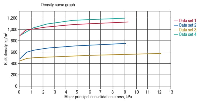
Figure 3: In a density curve, the x-axis shows the consolidating stress, and the y-axis shows bulk density
Flow function test
The vane lid is used to perform the flow function test. Powder strength is measured as “yield stress” by shearing particles trapped in the lid pockets against particles in the shear cell. Powder strength data at each consolidating stress are plotted on the graph in Figure 4 to produce a graph called a “flow function.” The solids-handling industry has established regions of flow behavior, as indicated in the figure, ranging from “free-flowing,” along the x-axis, to “non-flowing,” along the y-axis. Powders that are likely to exhibit flow difficulty in solids-handling processes are typically those that fall into the “cohesive” or “very cohesive” categories. These powders would be primary candidates for flow-aid additives to reduce internal friction between particles.
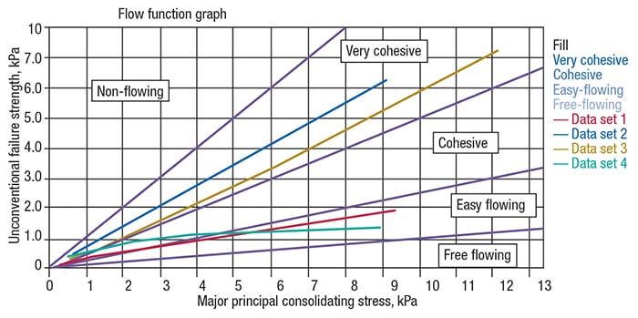
Figure 4: Powder strength data at each consolidating stress are plotted to create a flow function graph
Wall-friction test
The wall friction lid is used for this test. The material of construction used for the lid surface is based on actual hopper design — instrument vendors provide a range of offerings for different grades of steel and plastic routinely used in hopper construction. The test method for wall friction measures interfacial friction between the powder sample and hopper wall material at increasing consolidation stresses. Figure 5 shows a graph of wall friction behavior for various powders. Wall friction angles above 30 deg are considered high, and may lead to flow difficulty in powders.
One important point to note about hopper walls is that powder buildup may occur over time during processing. This can be simulated in the wall friction test by conditioning the lid accordingly and measuring the change in yield stress between the lid and powder sample. The general observation is an upward shift in the curves shown in Figure 5, which means greater resistance as powder slides down the hopper wall during discharge.
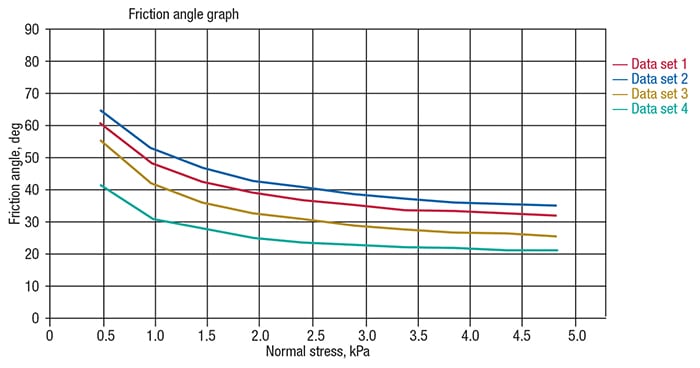
Figure 5: Different powders will show different wall-friction behaviors
Arching dimension and ratholes
Critical arching dimension is a conservative calculation of powder in mass flow that describes what conditions are necessary to build a stable bridge over the hopper outlet, thereby restricting discharge. The method for making this determination involves identifying the “critical consolidating stress.” Software provided by instrument vendors will establish a hypothetical line, referred to as a “flow factor,” which intersects the flow function. The point of intersection is known as the “critical consolidation stress.” Given this value, it is possible to perform calculations to determine the arching dimension and rathole diameter.
Hopper half angle for mass flow
By integrating data from both the flow function and wall friction tests, it is possible to calculate a value for the hopper half angle that will enable mass flow behavior to take place. Software provided by instrument vendors automatically performs this calculation.
Practical design considerations
Some powders require such steep slopes for hopper half angle (greater than 80 deg relative to horizontal) that equipment designs capable of meeting the requirement are not practical. These designs would result in discharge hoppers at the bottom of the bin that could be taller than the bin itself.
Many processors at solids-handling facilities are limited to the use of equipment that is already in place, and cannot make design changes to replace equipment. Two possible alternative options for finding solutions to flow problems could include changes in hopper wall material or an increase in cleaning frequency for the hopper surface.
Another approach for improving flowability is to incorporate additives into the powder formulation. Similarly, mechanical-assist devices, such as vibration and aeration, are other possible considerations. Trade-offs must be evaluated between the cost of these interventions versus the consequences of the lost processing time due to flow stoppages related to equipment downtime or poor product that requires rework.
The objective is to know before each process run what difficulties lie ahead. The flow function test has been streamlined to under 20 minutes for five consolidation-stress setpoints and under 12 minutes if two consolidation-stress setpoints are practical for providing a quick go/no-go assessment. This test gives a useful indicator for potential problems and puts the processor in a better position to respond in advance, thereby avoiding unexpected stoppages.
Edited by Scott Jenkins
Editor’s note: For more information on shear-cell testing, see Chem. Eng., April 2016, pp. 50–59, and Chem. Eng., January 2016, pp. 58–63.
Author
 Robert G. McGregor is the director of global marketing at Ametek Brookfield Instrumentation and Specialty Controls Division (11 Commerce Boulevard, Middleboro, MA 02346; Phone: 508.946.6200 ext 7143; Email: [email protected]; Website: www.brookfieldengineering.com). McGregor holds M.S. and B.S. degrees in mechanical engineering from the Massachusetts Institute of Technology (MIT) in Cambridge, Mass.

Feeder Design for Solids Handling
Processes involving the movement of bulk solid materials require careful consideration of the feeder equipment design, including how the feeders work with various bins and hoppers
The importance of feeder design in maintaining reliable material flow in solids handling processes can easily be underappreciated and underestimated, but ignoring the feeder will likely result in costly and disastrous outcomes. Feeders are designed to control solids flow, but they also need to work well with the bin, hopper or silo system associated with the process. Engineers can expend great effort and resources to evaluate a material’s flow properties, design the best bin for those properties and spend signficant funds on liners or steep hoppers, only to have all the money and effort wasted by an improperly designed feeder.
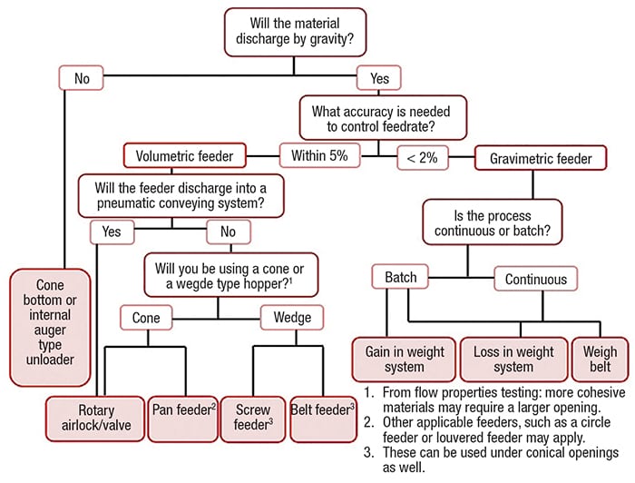
The bin and feeder must work together to ensure uninterrupted flow from the bin. To foster a deeper understanding of the importance of feeder design, this article discusses material flow basics, flow patterns, the key role of bin design, the types of feeders commonly used and devices available in the marketplace. In addition, it includes a list of feeder-related “dos and don’ts” and finally a flow chart used to determine the correct feeder for an application (see flowchart, below).
Flow problems
Several flow problems can occur in bins and silos, including the following:
- No flow due to arching and ratholing
- Erratic flow
- Flooding or flushing
- Flowrate limitations
- Segregation
These problems are discussed further below.
Arching and ratholing. In some situations, flow is initiated from the bin, and it either does not flow at all or perhaps flows for a short time and then abruptly stops flowing. When this occurs, the material is in a no-flow condition due to the formation of an arch or a rathole (Figure 1). If an arch forms, consider that this arch is strong enough to support the entire contents of the bin or silo and stop the flow. An arch is sometimes referred to as a bridge or dome. When material arches, sometimes the only way to address it is to employ a drastic means of flow promotion, such as vibrators, fluidization and unfortunately, sledgehammers.
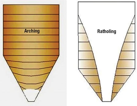
Figure 1. Arching and ratholing can result in no-flow conditions for a solids handling process
Typically, a rathole develops when flow is initiated and the material flows for a short time, then stops. Consider that friction develops between the material and the hopper wall surface such that, if the hopper wall is too rough or too shallow (or both), the material will not slide. When this occurs, a flow channel develops. Usually this channel forms straight up into the material, but it can also travel off to one side. If the solid material has cohesive strength, the flow channel will empty out and form a stable “pipe” that is referred to as a rathole. Like arching, collapsing a rathole requires extreme measures. The effects of these measures on the structure of the bin or silo should be considered. Collapsing ratholes can release tremendous amounts of material, which can cause silos to fail.
Erratic flow. The problem of erratic flow is a combination of arching and ratholing. If the material in a bin ratholes, and a flow-aid approach is used to collapse the rathole, a bridge may still form. Consider that when a rathole collapses, the material impacts the outlet with tremendous pressure. In some cases, the force of the collapsing material is so great that a stable arch forms due to the impact pressure. This type of flow problem can adversely affect flowrate, cause unwanted variations in bulk density and can potentially affect the structural integrity of the bin.
Flooding or flushing. Fine powders are easily fluidized. When a rathole forms and material is knocked off the top of the flow channel, this material will be highly fluidized and uncontrollable. Also, if the level detector indicates a low level (due to ratholing), it will call for more material to fill the bin. As this material enters the rathole, it will become highly fluidized. When one of these two conditions occurs, the feeder at the outlet of the bin, which is designed to handle a solid, will be overcome with fluidized product and will likely flush uncontrolled out of the feeder.
Limited discharge rate. Fine powders are less permeable than coarser materials. This creates a problem with air passing through the particles easily. For example, let’s say a discharge rate of 10 ton/h is required and when the feeder is turned on, the rate is actually 2 ton/h. Normally, discharge rates can be raised by increasing the feeder speed. However, when this is done, the discharge rate increases to 3 ton/h no matter how fast the feeder speed is increased. What has happened? When the bin is filled, the air within the voids of the solid material is squeezed out through the bin filter at the top. As flow is initiated, more air is squeezed out of the material voids. Also, when material enters the hopper, it dilates or expands, creating a vacuum. Nature tries to satisfy this condition by bringing air in from the outlet below. This counter-current airflow slows the material down and limits the flowrate.
Segregation. Separation of particles, or segregation, occurs when a product composed of different particle sizes or densities (for example, grain with fines or dust) separates. The major cause is sifting, where fine particles of a solid sift between coarse particles. As an example, upon forming a pile of material with differing particle sizes, typically, the fine particles would concentrate under the fill point, while the coarse particles would role or slide to the outside (Figure 2). There are several other mechanisms of segregation that can be troublesome if uniform density or mixed material is required for a process.
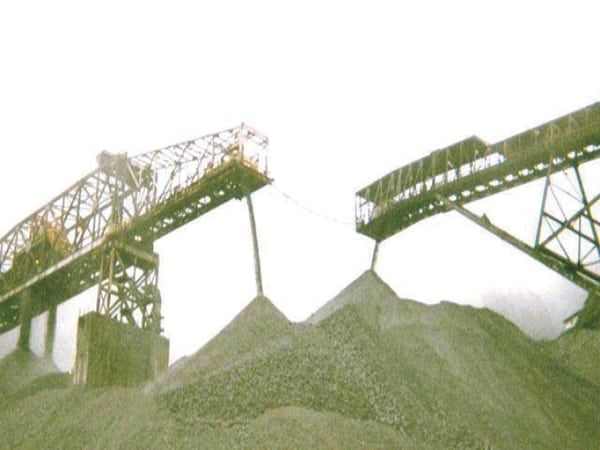
Figure 2. Segregation can occur when a solid product consists of different particle sizes. When piling, as shown here, finer particles tend to concentrate under the fill point, while coarser material tends to roll to the outside
Flow patterns
There are two major types of flow patterns for solids in a bin or silo: funnel flow and mass flow.
Funnel flow. A material flows in funnel flow mode when only some of the material is flowing, while the rest remains stagnant along the walls of the vessel. Suppose that the hopper walls slope at 45 deg or even 60 deg. In most cases, these hopper walls at these angles are not steep enough to ensure solids flow along them. The hindrance of solids flow occurs because of the friction that develops between the bin wall and the material. When the walls are too shallow or too rough to overcome friction, many of the flow issues described previously can result (Figure 3). The flow sequence for funnel flow can be characterized as “first-in-last-out,” where the first material in the bin is typically the last to discharge. If the material is cohesive, it may bridge or rathole.
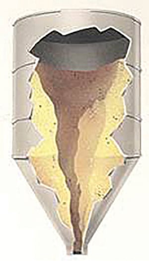
Figure 3. When hopper walls are not sufficiently smooth or steep to overcome friction of the solids on the walls, flow problems can result
Funnel flow bins are suitable for coarse, free-flowing materials that do not degrade. Additionally, they can also be used with solids that are not susceptible to segregation problems. The bin’s live or usable capacity is reduced with funnel flow, and ratholes also can potentially cause structural failure.
Material such as plastic pellets or coarse, dry sand would typically be suited to funnel-flow applications. The major benefit of funnel flow is that the headroom requirements for the bin are reduced, as are fabrication costs. However, solids flow problems usually far outweigh the benefits, as most fine powders do not flow well in funnel flow conditions.
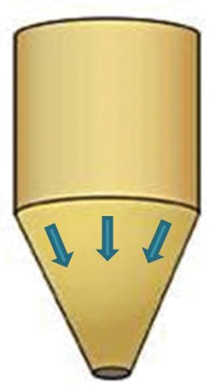
Mass flow. A material flows in mass flow mode when all the material in the bin moves when any of it is withdrawn. The solid is capable of flowing along the walls because they are steep and smooth enough to overcome the friction that develops between the solid and the wall surface (Figure 4). A rathole cannot form, simply by definition — all the material is in motion when discharging. Note that arching is not eliminated by mass flow. If a material has sufficient cohesive strength, it may arch over the outlet.
Figure 4. In mass flow situations, all of the material moves when any of it is withdrawn from the hopper
Mass flow bins are suitable for cohesive solids, fine powders, materials that degrade or spoil, and solids that segregate. Particles that have segregated by sifting (side to side segregation) flowing in a mass flow bin will be remixed as they discharge through the outlet. Fine powders that tend to flood are allowed to de-aerate in the bin and flow in a controlled manner.
Bins designed for mass flow develop a “first-in-first-out” flow sequence and the entire contents of the bin are fully live.
It is critical that the feeder pull material from the entire cross-sectional area of the bin outlet. If this does not occur, a funnel-flow pattern will develop in a bin that was designed and modified for mass flow.
Hopper shape: wedge versus conical
Conical shaped hoppers are commonly used to store and handle bulk solids. Conical hoppers required to ensure mass flow usually have steep hopper slopes and smooth surfaces. On the other hand, wedge hoppers require less steep hopper walls to ensure mass flow. Examples of wedge hoppers are transition and chisel hoppers. Each of these incorporates a slotted or elongated opening (Figure 5). Typically, a wedge-type hopper can be about 11 deg less steep than a conical hopper and still promote flow along the walls (that is mass flow).
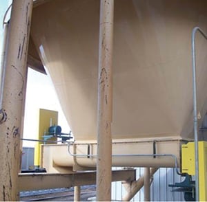
Figure 5. Wedge-shaped hoppers often require less steep hopper walls to achieve good flow
Some advantages of wedge hoppers over conical hoppers are the following:
- Wedge hoppers do not have to be as tall as conical hoppers to ensure mass flow
- Wedge-shaped hoppers require a smaller slot width than the diameters of conical hoppers to prevent arching. Consider also, that this allows the use of a smaller feeder
- Wedge-shaped hoppers also allow material to flow at higher discharge rates because of the increased cross-sectional area created by the slotted
- opening on this type of hopper
Disadvantages of wedge-shaped hoppers that must be considered include the following:
- Wedge-shaped hoppers may cost more to fabricate than one with a conical geometry
- The feeder used to discharge material must be capable of discharging material over the entire cross-sectional area of the slotted outlet. This requires a specially designed screw or belt for use with the hopper
- This feeder may be more expensive than one used for a circular opening
- This feeder will discharge offset at its end. Centerline discharging from the bin may better be served by a conical configuration
Volumetric feeder types
A volumetric feeder allows material to be fed on volume-per-time basis. Typically, volumetric feeders will provide accuracies within 2 to 5%, which may be more than adequate. Volumetric feeders work well when a material has a fairly consistent density, meaning the weight per volume remains constant. In controlling the feedrate, the volumetric feeder assumes the density remains the same and relies on feeder speed to control the rate. In mass flow situations, material will be discharged with a fairly uniform density due to the consistent pressure history the material will have experienced.
With most feeders, gravity flow from a bin discharges to the feeder. Even the best feeder will not work if the material arches above the bin outlet. And even the best feeder will not overcome a poor bin design. Common volumetric feeder types include screw feeders, belt feeders, rotary valves, pan feeders, louvered feeders, circle feeders, and Laidig-type unloaders.
Screw feeders. A screw feeder uses a rotating auger contained in a trough. The auger is a shaft with flights wrapped around it. As the screw rotates, material shears or slips on itself, and on the surface of the flights, advancing forward. A screw pitch is made up of one 360-deg wrap of the flight. The distance from the start to end of the pitch will determine the volume of material that can be transported for every revolution of the screw. The discharge rate of a screw feeder can then be changed by adjusting how fast the screw rotates, which is typically measured in revolutions per minute (rpm).
A screw feeder is well suited to a wide range of both fine and coarse materials. Because screw feeders are enclosed, they are well suited to handle dusty or hazardous materials. In addition, screw feeders are not ideal for friable materials, where particle attrition is undesirable. However, screw feeders require very little headroom, which is helpful when there are process-height restrictions.
A screw feeder is typically used with wedge-type hoppers with slotted outlets. To maintain mass flow, a screw feeder must have an increasing capacity in the discharge direction. This can be accomplished by varying the flight pitches and altering the screw shaft by use of a conical shape (Figure 6). The goal is to ensure a uniform withdrawal of material from the bin, achieving a fully active outlet. The screw shown on the right side of Figure 6 however, is a constant-pitch screw, which develops a preferential flow channel over the back flight. The material over the front of the screw is stagnated.
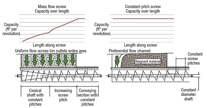
Figure 6. Varying the flight pitches and altering the screw shaft in a screw feeder can maintain uniform withdrawal of material from a container
A mass-flow screw feeder has a conveying section, which means that its discharge placement is offset from the centerline of the bin. Additionally, exceptionally long conveying sections may result in unacceptable shaft deflections and will increase the power requirements to turn the screw.
Belt feeders. A belt feeder consists of an endless moving belt, idlers that support and guide the belt, one or more pulleys to control the belt tension, a drive to power the belt, and the supporting structure. The top of the belt will carry material from the bin outlet to an offset discharge point. The material volume conveyed by the belt is often set by an adjustable gate below the bin outlet. This gate will shear the material to a constant depth and width. The speed of the belt is used to adjust the material feedrate.
Like the screw feeder, a belt feeder is often required for bins with slotted outlets. To maintain a mass-flow pattern, a belt feeder must increase in capacity in the discharge direction. This can be accomplished through a properly designed interface between the bin outlet and the belt. This interface uses gradually rising interface from back to front. This allows more material to be deposited on the belt toward the discharge end of the bin. Additionally, the interface increases in width from back to front, allowing the material to stream onto the belt uniformly and maintaining a fully live bin outlet (Figure 7).
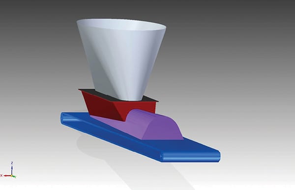
Figure 7. Belt feeders, like the one shown here, can handle a wide range of materials
The belt feeder can handle a wide range of materials, including friable materials, very cohesive materials and sticky or fibrous materials. A belt feeder is not well suited for fine powders or other materials that are prone to flooding or those that are extremely dusty. Some materials may require a belt scraper or some other cleaning device to deal with material buildup on the belt. Belt feeders also demand regular maintenance and cleaning.
Rotary valve feeders. A rotary valve feeder (also known as a rotary airlock) consists of a series of pockets attached to a rotating shaft. The feeder has a driven rotor with vanes attached to it that form the pockets, and is enclosed in a cylindrical fixed housing. As the rotor spins, material from the bin fills the pocket by gravity. Once the pocket rotates 180 deg to the bottom of the valve, gravity causes material to drop out of the valve. Typically, rotary valves are used as airlocks to feed material from a bin into a pneumatic conveying system. They are capable of providing an air seal due to the tight clearance between the vanes and the housing. This seal prevents countercurrent, high-pressure air from permeating up into the bin and interrupting material flow.
As the pockets begin filling with material, air displaced from formerly empty pockets may cause some erratic material flow from the bin. Typically, this is observed as a reduction in material flow or as material flooding. To alleviate this problem, newer rotary valves include a vent line designed to send the displaced air to either the top of the bin or to a dust collector. A vent line may need to be added if the rotary valve does not have one. Rotary valves typically feed preferentially from one side of a bin, as the pocket fills with material and cannot take any material from the other side of the outlet. To restore mass flow, the bin outlet must be made fully live, where the material is uniformly withdrawn from the bin outlet. This is typically accomplished by adding a vertical section between the bin outlet and the rotary valve. The preferential flow channel will expand upward through the vertical section, and uniform material flow will be established (Figure 8).
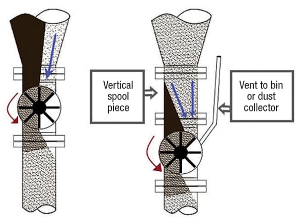
Figure 8. A rotary valve feeder has a motorized rotor that spins, allowing material from the hopper to fill the sections
A rotary valve will be sized based on the outlet and required feedrate. Feedrate can be adjusted by changing the pocket size and the rotary valve rotations per minute. Rotary valves are suited for bins with square or circular outlets. They are typically not applicable for very cohesive materials, friable materials, fibrous materials, or materials with large chunks. Any material that can jam or stick inside of the pockets may prove problematic. Another concern is very abrasive materials that can wear away at the clearance between the vanes and housing. Wear will diminish the air seal and change the accuracy of the feeder over time, because material could leak and bypass the rotating pockets.
Pan feeders. Pan feeders (also called vibratory pan feeders), use a pan with a vibratory drive attached to vibrate and feed the material. As the pan feeder vibrates, material is thrown very slightly up and forward. Material feeds from the outlet into the tray and can be conveyed a short distance to some discharge point (Figure 9a).
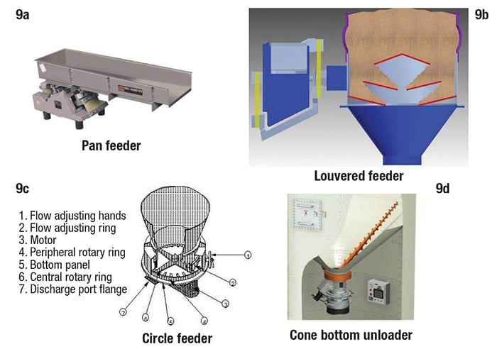
Figure 9. The feeder types shown here use a variety of mechanical strategies to maintain solids flow
Vibratory feeders can handle a range of materials and achieve a wide range of flowrates. Increasing or decreasing the vibration is typically used to control the feedrate. Very fine materials may not be suited to vibratory feeders since they are prone to flooding. Dusty materials can be accommodated by an enclosure over the pan. Actual flowrates for a given material will be influenced by particle size, cohesive strength, wall friction and a variety of other factors. Depending on the material, additional testing may be required to ensure proper feeding and control.
Louvered feeders. A louvered feeder attaches directly to an outlet and uses a series of internal louvers (or slats) that gently vibrate to discharge material. The louvers will be spaced and angled such that when not vibrating, material will find its angle of repose and not discharge. A vibratory drive attached to the outer housing of the enclosed louvers provides discharge. Beneath the louvers is a chute that directs the material stream to the desired outlet.
The housing of the feeder is supported by cables attached to the bin. The feeder has a flexible skirt to seal and isolate the bin from vibrations (Figure 9b).
Circle feeders. A circle feeder is a unique table-style feeder that uses a rotating vane to push material to an outer perimeter and one or more discharge points. It consists of a slow rotating vane, an enclosed housing, discharge ports, and a driving mechanism (Figure 9c). The feeder mounts directly on the outlet and uses a number of flat blades spaced equidistantly, making up the vane, to work material to an outer-perimeter chamber and then to outlet ports. These feeders have excellent precision and work well with a large variety of materials.
Cone-bottom or auger-type unloaders. A cone-bottom or auger-type unloader consists of an internal auger that sweeps around the cone bottom of a bin. The auger undercuts material in the bin, feeding it to the center outlet. The auger drive is located outside of the hopper, keeping it out of the material stream and accessible. These types of feeders are ideal for feeding difficult-flowing or very cohesive materials that might otherwise bridge over the outlet (Figure 9d).
Feeder Dos and Don’ts
The following represent practices to employ, and others to avoid, when designing and choosing feeders and related equipment.
Do measure flow properties. Material flow properties are required to determine your material’s cohesive properties, wall friction properties and compressibility. These properties provide necessary information for proper design of your feeder.
Don’t choose the wrong feeder. You would not want to use a belt feeder when handling floodable materials. Likewise, you would not use a screw feeder to handle friable products.
Do design for mass flow. The bin and feeder must work in unison. If the bin is not designed to ensure mass flow, the feeder will be dealing with funnel flow and ratholing, erratic flow, flooding and segregation issues. Likewise, if the feeder is designed improperly, flow from the bin will be affected negatively.
Don’t assume that one feeder is suited to all solids. You may need to discharge at high flowrates. This would likely require a slotted opening with either a belt or screw. If you need to discharge to a pneumatic conveying system, a rotary airlock will be required to seal against a positive pressure gradient. You would not want to use a belt or screw to do this.
Do consider material consistency. If you are handling a low density product or require low discharge rates, you may want to consider a pan feeder to provide uniform discharge. If your material is dusty or toxic, a properly designed screw feeder will be useful.
Don’t mistake a conveyor for a feeder. Often, conveyors are assumed to be feeders. A feeder is designed to operate nearly 100% full; whereas, a conveyor would typically operate at less than, say 40% capacity to provide conveyance.
Do account for loads on a feeder. Feeder loads can be tricky. For instance, consider a bin with a properly designed mass-flow screw feeder that has initially been filled with your material. Be aware that initial fill loads require increased torque to turn the screw. This initial fill pressure can require 2.5 times the running torque to start the screw.
Don’t use constant-pitch flights. Constant-pitch screws are notorious for developing preferential flow channels. The back flight (away from the discharge end) fills with material and the succeeding flights being constant pitch, do not have the capacity to take any more material and material does not flow over the entire bin outlet, only the back.
Do ensure increasing-capacity geometries. A screw or belt’s success is dependent on increasing the capacity of the equipment in the discharge direction. With a screw, this is done by varying the flight pitches, and on a belt, by using an interface design that provides the increase in capacity required for uniform flow.
Don’t sacrifice quality for low cost. We all have to work within budget constraints. But purchasing an incorrectly designed feeder because it was less expensive can lead to severe handling problems down the road.
Gravimetric feeder types
A gravimetric feeder allows for material to be fed on a weight-per-time basis (rather than volume-per-time). Gravimetric feeders achieve a greater degree of accuracy than volumetric feeders. If a system or process requires accuracy closer than±5%, a gravimetric feeder will be able to achieve 0.25 to 0.5% accuracy. Unlike volumetric feeders, gravimetric feeders will allow for density variations within a material. Common gravimetric feeders are weighbelt feeders, loss-in-weight (LIW) feeders, and gain-in-weight (GIW) feeders.
Weighbelt feeder. A weighbelt feeder is much like the volumetric belt feeder. The weighbelt feeder incorporates some type of weighing platform. Typically this will be one or more load cells with one of the belt’s support rollers mounted to it. The weighbelt may be directly under a bin or be fed by a prefeeder. The feeder uses both the belt speed and the continuous weight measurement to determine the amount of material being delivered on a weight basis.
Weighbelts work well for both continuous or batch processes. Weighbelts are sensitive to material buildup, which will result in a loss in accuracy and may require maintenance to clean, adjust and recalibrate the feeder. Weighbelts can handle a similar range of materials as that of belt feeders. Also, they are typically not suited to materials that are sensitive to flooding.
Loss-in-weight system. An LIW system controls the feedrate based on the weight of material taken away from a hopper. LIW systems comprise three components: a refill device, a LIW hopper and a feeder. The refill device, which could be a hopper with a slide gate or a volumetric feeder, will quickly fill the LIW hopper. Once the hopper is filled, weighing begins. As discharge begins, the load cells measure the loss in weight of the product being discharged to the process.
A LIW system accommodates both continuous and batch processes. For a continuous process, when the hopper is refilling, the feeder will switch to volumetric mode. Once the hopper has been filled again, the feeder reverts to gravimetric mode. Another option is to use dual LIW hoppers (no freeze). While one hopper is discharging, the other is filling, so no volumetric mode is necessary.
Gain-in-weight system. A GIW system is strictly a batch system. It weighs the total material filling a container. Material is fed into a container on a scale or load cells, until the desired amount is reached. Once the amount is reached, filling will stop and the GIW system will be emptied to a process. Most materials will work with a GIW system; however, it is vital that the GIW container be completely emptied to maintain accuracy.
Edited by Scott Jenkins
Authors
 Joseph Marinelli is president of Solids Handling Technologies, Inc. (1631 Caille Ct., Fort Mill, SC 29708; Phone: (803) 802-5527; Email: [email protected]; Website: www.solidshandlingtech.com). Marinelli is a bulk materials handling expert who has taught hundreds of highly acclaimed engineering seminars. Since 1972, he has been active in testing bulk solids and consulting on materials handling systems design. Marinellii has previously worked with Jenike & Johanson, Inc., world-renowned experts on solids handling. Marinelli received his B.S.M.E. degree from Northeastern University in Boston, Mass. Marinelli has also worked for manufacturers of solids handling equipment, such as feeders and silos. This background provides a unique blend of consulting and manufacturing experience to solve solids flow problems. He lectures frequently, teaching courses on solids flow principles and flow property testing, and has authored several papers and an encyclopedia section on the subject. Since 1997, he has been involved with very popular seminars at the University of Wisconsin in the areas of bin and feeder design and solids flow property testing. He is also a columnist (“Powder Perspectives”) for the website, www.powderbulksolids.com
 Scott Miller is senior consultant for Solids Handling Technologies, Inc.(same address as above; Phone: (803) 517-0058; Fax: (803) 802-0193; Email: [email protected]). Miller works closely with clients to provide the expertise required to evaluate and solve their solids flow problems. He analyzes flow properties test data produced by his employer’s testing laboratory, and writes flow reports describing the parameters necessary to resolve flow problems. Miller is also actively involved in providing practical, conceptual design recommendations to clients. Miller received his B.S.M.E. degree, with a minor in mathematics, from Geneva College in Beaver Falls, Pa. His background as a plant engineer at a power-generation facility in Pennsylvania provides valuable experience handling anthracitic waste, planning outages and providing solutions to typical coal-handling problems.